
Acceleration system for Hyperloop trains (2019-2020)
Acceleration system for Hyperloop trains

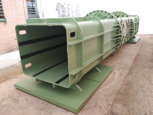
Fig. 1. Technology for Hyperloop from the Spanish company ZELEROS.


SEA TITAN Project (2018-2020)
Surging Energy Absorption Through Increasing Thrust And efficieNcy (SEA TITAN)
H2020 LCE 2016-2017. Topic LCE-7-2017
| Participant Nº | Participant Organization name | Acronym | Country |
|---|---|---|---|
| 1 (Coordinator) | Wedge Global S.L. | WEDGE | Spain |
| 2 | CIEMAT | CIEMAT | Spain |
| 3 | WavEC - Offshore Renewables | WavEC | Portugal |
| 4 | CorPower Ocean | CORPOWER | Sweden |
| 5 | Centipod LTD | CENTIPOD | UK |
| 6 | Hydrocap Energy SAS | HYDROCAP | France |
| 7 | OCEM Energy Technology srl | OCEM | Italy |
| 8 | Columbus Superconductors | CLBS | Italy |
| 9 | Engie - Cofely Fabricom | ENGIE | Belgium |
| 10 | EDP Centre for New Energy Technologies | EDP CNET | Portugal |
| 11 | Asociación Española de Normalización | UNE | Spain |
The overall objective of the SEA-TITAN project is to make a step change in the wave energy sector by designing, building, testing and validating an innovative second generation Direct Drive Linear Electric Generator Power Take-Off solution: an Azimuthal Multitranslator Linear Switched Reluctance Machine (AMSRM). This development is based on a new configuration and geometry of a first generation Multitranslator Linear Switched Reluctance Machine developed by some of the proponents some years ago. The development aims at achieving high continuous and peak force densities and also high efficiencies with application to multiple wave energy conversion technologies through collaboration with different wave energy developers and industrial partners with strong track record on technology.
The technical concept underpinning SEA-TITAN proposal comprises the development of a disruptive linear electric direct drive power take-off (PTO) for wave energy converters (WEC). The innovative type of PTO proposed is an Azimuthal Multitranslator Switched Reluctance Machine (AMSRM), presented in Figure 1‑2, that will be complemented by the appropriate power electronic converters and control platform to develop the power transformation from the mechanical power in the WEC to the electric power supplied into the grid.
This non-patented Wedge Global invention is both novel and inventive, achieving three substantial improvements compared to current tubular generators and non-direct drive systems: a) concentrated and static coils and simpler translator made just of magnetic laminations that means a robust and cost effective solution, b) higher density force without the use of permanent magnets, by using a multitranslator topology, c) higher power density that means a compact PTO able to fit in the geometry of most wave energy converters.
These improvements will contribute to increased energy production, reduced system mass, increased reliability and increased availability. Together these innovations will reduce significantly the Levelized Cost-of-Energy (LCOE) delivered by the SEA-TITAN crosscutting PTO system.
SEA-TITAN is created to accelerate the advent of wave energy by opening the innovation process to the open source community by means of the implementation of an open business, which facilitates the technology development, providing free use of patents by other competitors (Wave Energy Technology Developers), the ones who are in the Consortium or additional companies willing to join in the future.

Figure 1 Integration of the AMSRM based PTO in a Heaving Point Absorber

Figure 2
Overall Structure of the Work Plan
SEA-TITAN project is structured in 7 Work Packages (WP): one dedicated to coordination (WP0), five comprising the technical core of the Project (WP1-WP5), and one related to dissemination, communication, exploitation of results and standardization (WP6). The WPs are related between each other as presented in Figure 3‑1.

Figure 3 1. Overall structure of the Project
The technical part of the project starts with the identification of the technical requirement of a higher force density power take-off (PTO) as well as peak forces, analysed in three different types of wave energy converters (WECs). In WP1, 4 different technologies of point absorber devices will be modelled in two sea locations each (UK, France, Portugal and Spain), defining a set of 8 scenarios in the west coast of Europe, where the wave resource is more promising, covering a width range of application for the proposed PTO. Considering also a set of restrictions, such as volume and cost limitations, a scalable PTO module will be defined, as well as a PTO prototype to be developed. In WP2, from the previous specifications, a detailed design of the complete PTO based on the concept of azimuthal linear switched reluctance machine (AMSRM) will be developed, including the power electronics and control to operate the system and connect it to the grid. A complete prototype of the new design of PTO will be fabricated in WP3. Different partners will take care of the linear generator, power electronic converters and control platform, respectively. The complete novel prototype of PTO will be tested in laboratory environment during WP4, emulating real conditions (hardware-in-the-loop scheme) of the 6 scenarios defined in WP1, by using a hydraulic actuator and a control platform to reproduce the on-line conditions. Complete information of the performance of the new PTO (force limits, efficiency map, thermal behaviour and mechanical vibrations) will be obtained from these experimental tests and the PTO models obtained in WP1 will be updated and fine-tuned.
Based on the specifications defined in WP1 and some design ideas from WP2, a parallel development of a conceptual solution of linear generator based on superconducting windings will be accomplished in WP5. This alternative solution deals with the benefit of increasing the energy generated due to the no force limitation at the PTO, and can be implemented into the AMSRM without specific limiting requirements to the geometry.
Both the PTO solution based on AMSRM and the superconducting PTO will be especially useful for the potential final users included in the consortium or in the External Industrial Exploitation Board (EIEB), who will evaluate the possibilities of commercialisation of the new PTO solutions in the market of the wave energy converters. That will be accomplished in the core of WP6. Moreover, WP6 will comprise the communication about the project, dissemination of the results in the scientific and industrial communities, as well as analysis of the innovative character of the solution, and management of the intellectual property of the results among the members of the Consortium.
SPAII WEC System Agnostic PTO (2018-2019)
The project provided for the company WEDGE GLOBAL is based on the development of a power take-off (PTO) to be integrated in a certain type of wave energy converter for the American company DEHLSEN ASSOCIATES.
The scope of the CIEMAT participation is divided in three different actuations:
- The analysis of the output data of the wave energy converter in order to define the PTO characteristics based on a power losses model.
- Design of the power electronic converters to drive the linear generator used as PTO
- Development of the control algorithm of the PTO and assistance to the laboratory tests of the complete system.
1. Analysis of force-velocity data
A set of 114 cases of study under different conditions of Hs and Te have been the starting point for this analysis. Force and Velocity have been presented together for each case of study and Mechanical Power has been calculated from them. Moreover, Electric Power has been also calculated, considering the PTO model.

Figure 1. Set of data numbered and organised by Hs and Te. Occurrence of the different types of data provided.
Generator Design
The PTO proposed for the adaptation to the Dehlsen Associates wave energy converter is based on a configurable and scalable concept of linear generator developed by Wedge Global, the W200. The current magnetic design is developed to provide a 200 kN force with 1m/sec velocity. The aim of this section is to scale up the linear generator to provide 600 kN force, 1.5 m/sec velocity but pursuing an improvement in the performance of the PTO.
The evolution of the efficiency when modifying the design parameters, such as number of virtual machines, active length and number of turns per coil has been studied. The active length and number of virtual machines affect to the force developed by the PTO, thus, in order to maintain the 600 kN required, modifying the active length means changing the number of virtual machines in consequence. This way, fixed combinations of both parameters have been determined for the study.
A virtual machine is defined as a basic electromagnetic module that is part of the linear generator. A particular solution has been selected with 16 virtual machines and 24 turns per coil in the linear generator. A discussion of the dimensions of the PTO, related to active length, width and height (in the direction of the height of the WEC, perpendicular to the plane of the sea surface) is also presented in the study. Generator width has been considered fixed since it affects to the magnetic circuit and it has no changed. The active length dimensions curve is obtaiend as well as the height. All points provide the required force in the linear generator.
Conclusions
After the analysis of the data supplied by Dehlsen Associates, in order to evaluate the performance of the complete PTO by using a losses model, some important conclusions have been obtained:
- The analysis reveals clearly that the operation of the system under the current control strategy leads to very high forces and losses, which limit very severely the amount of electric energy that can be produced. These results are quite independent of the type of PTO used to convert the energy.
- Control strategy should be defined considering both the mechanical WEC and the PTO in order to achieve an optimal operation based in the electric power produced not the mechanical power. The improvement achieved when following this strategy is demonstrated in the bibliography.
- A global design of the complete WEC, also considering the PTO, should be accomplished in order to optimize the whole system and not only the mechanical part of the WEC. To accomplish the named “high level design” would require an integration of three elements together: the point absorber characteristics, the PTO and the control strategy. Any particular advance in any of the three separately will be useless.
2. Design of the power electronic converters
The second stage of the project consists in the calculation and design of the power electronic converter and control platform for the laboratory tests of the WEDGE linear switched reluctance generator. Although the calculation and design will be only focused on the generator-side converter at this stage of development, the rest of auxiliary systems required for the solution proposed for the laboratory tests are described. Previous validation of the performance of the linear generator together with the power electronics and the control is also demonstrated with the calculations developed during this work.
It is supposed that the linear generator will be mechanically moved with an external actuator that will provide the appropriate force, according to the wave profile and WEC characteristics provided by DEHLSEN and considered as environmental conditions. The linear generator will be moved and the mechanical power transformed into electrical power managed by the power converter and supplied to a certain DC-link of 450V. The generated power needs to be sent to the grid or dissipated into a dissipating resistor. Additional power transformer, power rectifier, grid protections and DC-charge circuit will be required.
Figure 2 presents a scheme of the different converters and modules used during the solution proposed for the laboratory test with WEDGE linear generator. The mechanical actuator will be connected the electric mains and will have its own control, according to the sea location conditions to be emulated during the tests. The generator-side converter (GSC) and the DC/DC chopper (CHP) to dissipate the generated power are presented in the figure.

Figure.2. Scheme of the solution proposed for the laboratory tests of the WEDGE Linear Generator.
The laboratory tests will be carried out with just one of the named virtual machines or single module of generator, which is related to the basic unit of three-phase linear generator.
A model will be used to define the semiconductors, the cooling system, the minimum velocity and a set of the most critical values from the point of view of power losses at the power converter. Moreover, an optimization procedure will be later carried out in order to define the optimal activation and deactivation angles for the generator phases according to a certain criterion (constant force and constant velocity for the maximum electric power operation point).
Figure 3 presents an example of one phase current obtained in the diode with the model under some specific conditions of force and velocity during generator mode.

Figure 3. Current waveform at the diode for certain conditions of force and velocity.
Figure 4 shows the results of the angles, mechanical and electric power, force and efficiency when evaluating the linear switched reluctance generator (LSRG) designed with the power converter. Maximization of the electric power extracted has been used as criteria for the optimization of the activation angles.

Figure 4. Activation and deactivation angles, mechanical and electric power, force and efficiency of the LSRG with the optimized angles.
3. Development of control algorithm to drive the PTO and assistance to the laboratory test
This stage is focused on the implementation of the control strategy for the linear generator at the digital control platform, based on a DSP from Texas Instruments F28335.
Figure 5 presents a complete scheme of the control to be implemented in the LLC.

Figure 5. General block diagram of the low level control tasks.
From the HLC, and through the communication port, it is given the force reference or command (F*), obtained from the general control strategy provided by DEHLSEN. Considering the electromagnetic characteristic of the linear switched reluctance generator, the force command is transformed into current command (I*). On other side, the position of the generator translator is measured by means of a 24bits absolute encoder, which digital signal is converted into position (s) and then into velocity (v). Position and velocity will be supplied through the communication port to the HLC to be managed.
Velocity is used together with the current command to get the activation and deactivation angles by using a look-up-table previously calculated with an optimization procedure explained previously.
On the other hand, the generator phase currents are measured and will be used in the modulation technique block. Also, the currents together with the phase voltages, temperatures and stroke limits are introduced in an alarms block which will inform to the operator or will take an automatic action depending on the consequences.
Finally, phase currents and voltages will be used to calculate the instantaneous generator power. A variable calculated by the LLC that will be sent to the HLC through the communication port. Although an electric power calculator is suggested to be included in the software of the LLC, it is recommended to use an external measurement of power, since the sample time required for an accurate measurement of power needs to be higher than the one used for the control programme. Nevertheless, the provision of the internal calculation can be useful for the general control strategy.
From the current command, current measured in each phase, activation and deactivation angles, position and alarms, the modulation technique is in charge of providing the switching pulses for the IGBTs of the three phases in the power electronic converter.
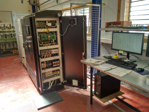
The factory acceptance tests (FAT) of the lineal generator and its power electronics have been carried out separately (in the factories of NEUREUS and ELINSA, respectively). After FAT, the complete PTO has been installed in the CIEMAT facilities for its setup and its characterization tests.
At present, the setup has been practically carried out, with de dynamic setup remaining. The final stage if the setup, the adjustment of the main control coefficients, will be carried out in the NREL facilities with an external actuator.
Static characterization tests have also been carried out, such as the measurement of force and the measurement of magnetic flux. The force measurement tests have been carried out by means of a mechanical locking system and a load cell. The magnetic flux measurement tests are carried out indirectly by integrating the electronic converters of an external current and voltage monitoring system.
(To be updated as the characterization and setup test are carried out.)
Proyecto SMARTWEC (2017)
![]()
SMARTWEC Project (RM16-XX-043): Global Optimization of point absorber Wave Energy Converters (Optimización global de convertidores de energía de las olas tipo absorbedor puntual).
![]()
The large amount of energy contained in the ocean waves, added to a better predictability and a less variable energy resource (compared to other renewable energies), leads the researchers, developers and industry companies to invest efforts towards the development of commercial wave energy devices.
The current situation of the Wave Energy Generation could be considered in a pre-commercial stage, where various types of WEC (Wave energy Converter) and technologies are being developed by different companies and continuous technology innovations are being developed and including in them. The main objective of these research and technology efforts is the consolidation of a wave energy market.
CIEMAT, after participating and collaborating in Spanish funded R&D projects, such as UNDIGEN, UNDIGEN+, or BRAKING-WEDGE, has continuing working in wave energy generation developments in the project SMARTWEC, which is funded by the regional public institution SOCERCAN (Society for the Development of Cantabria) in the program the program I+C=+C (call for cooperation projects in Marine Renewable Energies). The project has been funded with 391.420€.
In this context, Wedge Global, CTC and DEGIMA are collaborating (together with CIEMAT, as public R&D institute) in the project SMARTWEC with the main goal to analyse and develop different improvements in a WEC in order to obtain a reduction of the generation cost (obtaining a positive impact in the Levelized Cost of Energy). The project is focused in three main research lines: the analysis and development of a PTO ancillary system, the analysis and development of an active mooring system (both focused on increasing the generated energy) and the study and analysis of protective systems for the WEC passive structures (focused on improving the survival capacity). The final stage of the project includes an analysis of the techno-economic viability of a wave energy park, which could be implemented in a continuation of the project.
In this project, CIEMAT (in a first stage) has review and studied open source simulation tools. CIEMAT has developed an interface, which including auxiliary code, macros, etc., adapted to the project necessities and based on the programs NEMOH (https://lheea.ec-nantes.fr/logiciels-et-brevets/nemoh-presentation-192863.kjsp and WECSIM (https://wec-sim.github.io/WEC-Sim/. In addition, CIEMAT has modelled the existing WEC of WEDGE, has given support in the use of the source simulation tools and has helped in the development of the PTO ancillary system model.
In addition, CIEMAT has been developed a model of the linear electric generator of the WEC developed by Wedge Global. The model was based on the laboratory test carried out (by CIEMAT) in a previous project, and it included the definition of the wave energy extraction coefficients.
Finally, CIEMAT has adapted and used a proprietary code to define the WEC geometry for the wave energy park to be analysed. This proprietary code is based on an optimization algorithm, which solves the geometry design problem as an optimization mathematical problem.

Figure 1: Graphical User Interface developed for the open-source program NEMOH.

Figure 2: Results of NEMOH code.

Figure 3: Results of the proprietary code developed by CIEMAT for the WEC geometry design
SH2 (2015-2017)
Hybrid Energy Storage System for Hybrid Generation / SISTEMA HÍBRIDO DE ALMACENAMIENTO DE ENERGÍA PARA SISTEMAS HÍBRIDOS DE GENERACIÓN (SH2)
![]() Industrial interest towards energy storage systems for grid applications is increasing year after year. Microgrids and renewable energies are becoming the catalysts for a whole family of energy storage technologies such as batteries, supercapacitors and flywheels. These technologies are ready from the technical point of view, but they still lack some maturity from the industrial and economical point of view.
Industrial interest towards energy storage systems for grid applications is increasing year after year. Microgrids and renewable energies are becoming the catalysts for a whole family of energy storage technologies such as batteries, supercapacitors and flywheels. These technologies are ready from the technical point of view, but they still lack some maturity from the industrial and economical point of view.
One clear way to improve these storage technologies consists in hybridizing them, combining two or more systems whose technical characteristics are suitable to complement each other. This results in better performance and less oversizing, and therefore in a more optimized system. This improvement could make energy storage systems feasible and competitive for certain grid applications.
In this context, Gamesa Electric, CIEMAT and the University of Alcalá are collaborating in a project called “Hybrid Energy Storage Systems for Hybrid Generation Systems” (SH2) with the goal of developing a hybrid energy storage system (batteries + supercapacitors) which will be used to improve the quality of an isolated grid with hybrid generation (diesel + renewables). The resulting energy storage system will help achieve voltage and frequency control of the isolated grid with minimum diesel consumption.

In this project, CIEMAT is responsible for the design, dimensioning, assembly, testing and commissioning of the supercapacitors and their corresponding power electronics converter. CIEMAT’s R&D tasks include the design of an equalization hardware and software to prevent cell imbalances, the development of a supervisory system to monitor the supercaps state of health in real time (conceptually similar to the BMS used with batteries), the optimization of the cooling system to achieve maximum energy efficiency, and the development of the high-level control strategy which decides who to split the power between the two energy storage systems.
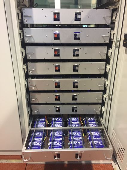
4 prototypes will be built during the project. The first 2 are scaled prototypes of up to 80V and 200A (30 cells in series). These prototypes have been used to perform extensive testing on the supercaps, including capacitance, ESR (equivalent series resistance), self-discharge, thermal behavior and cell unbalancing, both in healthy conditions and after suffering some electrical damage. The main differences between the two prototypes are the spatial distribution of the cells and the equalization hardware.
")
The 3rd prototype will increase the voltage level up to 650V (240 cells in series), reaching a maximum power of 125 kW. This prototype will also be extensively tested in the laboratory. Finally, the 4th prototype will double the number of cells by using 2 branches (2x240 cells), yielding up to 250kW. This last prototype will be tested in an operational environment (a microgrid with both conventional and renewable generation) under real working conditions, reaching a TRL of 7.
")
UNDIGEN (2011-2013) / UNDIGEN MAS (2014-2016)
UNDIGEN project: Functionality Tests of Ocean-Wave Energy Conversion System (IPT-2011-1770-920000).
![]()
In the last years, CIEMAT has been working on the conversion of ocean-wave energy into electric power. Electrical Engineering Division of the Technology Department has collaborated, through its Power Systems Unit, in R&D projects from 2011. It has collaborated in the project UNDIGEN of the 2011 INNPACTO National Funding Call, and in the project UNDIGEN MAS of the 2014 Collaboration RETOS National Funding Call, both of the Ministry of Economy and Competitiveness. The first project – UNDIGEN – has been based on testing the functionality of a new wave energy electric power generation system based on a linear generator and its electric drive, for which a 1:1 scale prototype has been tested on the coast of the island of Gran Canaria. The budget has been 2.5 M€, and CIEMAT has collaborated with the industry (WEDGE GLOBAL S.L. and FCC S.A.) and the Canary Island Oceanic Platform (PLOCAN). The second project – UNDIGEN MAS – which is currently active, is aimed at operating the generation system developed in UNDIGEN for use as a power supply for isolated loads by means of the integration of energy storage systems [1]–[3]. The budget is €430 K and again industry and PLOCAN have taken part.
 / UNDIGEN MAS (2014-2016)")
The Power Systems Unit has carried out collaborations directly with the industry from 2007, mainly consisted on analysis and characterization of an electric linear generator design for ocean-wave energy applications (designed by the industry), and including a preliminary design and development of the power electronics and DSP-based control platform for the linear electric generator.
In addition, under the R&D projects UNDIGEN and UNIDGEN MAS it has carried out a wave energy converter (WEC) design and modelling methodology, followed by an analysis to validate the hydrodynamic model. Most of the electric, electronic and control systems involved in the operation of the device have been designed, developed and tested. Finally, it has participated in the WEC tests at sea and in the subsequent analysis of the power data collected by the system.
The main objectives of these projects have been to:
- Develop a wave energy converter (WEC) that includes a new concept of power extraction system (power take-off– PTO) to demonstrate its functionality and robustness. This PTO is based on the use of a new concept of switched reluctance electric machine and its corresponding power converter, developments in which the group has extensive prior experience [4]–[7].
 / UNDIGEN MAS (2014-2016)")
- Validate the developed hydrodynamic model with the collected data for subsequent studies of the device at other sites.
- Obtain experimental power results, optimizing the system operation strategy in order to maximize the wave-energy extraction.
 / UNDIGEN MAS (2014-2016) Power Results")
These projects have developed energy generation and storage technologies and methodologies associated with ocean energy (in particular with the devices called point absorbers), thereby significantly improving CIEMAT’s capabilities in this area of renewable energies (one of the key issues of the research centre). Participation of CIEMAT in these projects demonstrates the Power Systems Unit capabilities and it significantly broadened its experience in this field of renewable energies. The tasks undertaken include:
- Study of the WEC dynamics in order to collaborate with the WEC point absorber geometry definition [8]–[12].
- Design and development of its associated power electronics, electrical and control equipment. The power electronics manages the generated electric power injected to the grid or to an isolated load.
- Preliminary tests of all the equipment in the laboratory and WEC startup at sea, as well as assistance during the testing at sea. The preliminary lab test allows to check the interaction between the equipment and how they operate together [5], [13]–[15]. These tests are indispensable due to the limited accessibility of their offshore location on the high seas, what reduces the startup period, the total project cost and the risks during the early stages of system operation.
The WEC developed in these projects is of the type known as point absorber [16], [17]. It consists of a buoy with two sections (a floating body called float and submerged body which consist on two bodies called spar and plate) that move vertically with respect to each other due to the effect of the forces resulting from the kinetic and potential energy variation of the ocean-waves.
 / UNDIGEN MAS (2014-2016)")
The motion of the float with respect to the plate is transformed into electric power via the PTO, which is housed inside the spar. Part of this generated electric power (by the linear generator and its associated power electronics) passes through an auxiliary power electronic converter to supply power to the electric consumptions included in the WEC (control, operation, measurement sensors, pneumatic system compressor, electro-valves and instrumentation system). There is also a battery set connected in this stage that will be used to ensure system operation. On the other hand, the rest of the power obtained from the generator, not required to supply power to auxiliaries or to recharge batteries, would be injected into the grid via an electronic grid converter and an underwater cable. In the above mentioned projects there has been no grid connection point or underwater cable, but rather the excess generated power is dissipated in an electrical resistance via a direct current converter. All the electronic converters, sensors and instrumentation and the operation of the entire system are managed by a control system based on microcontrollers and digital signal processors (DSP) that receive the system measurements, decide on the actuation of the different subsystems, control the power electronics and determine for the device all the defined operating modes.
 / UNDIGEN MAS (2014-2016)")
References
- M. Lafoz, L. Beloqui, M. Blanco, P. Moreno-Torres, G. Navarro, and L. García-Tabarés, “Dimensioning Methodology for Energy Storage Devices Applied to Wave Energy Converters,” in OSES 2015: Offshore Energy & Storage Symposium, 2015.
- P. Moreno-Torres, M. Blanco, G. Navarro, and M. Lafoz, “Power Smoothing System for Wave Energy Converters by means of a Supercapacitor-based Energy Storage System,” in 17th European Conference on Power Electronics and Applications (EPE’15-ECCE Europe), 2015.
- M. Lafoz, P. Moreno-Torres, L. Beloqui, G. Navarro, and M. Blanco, “Dimensioning Methodology for Energy Storage Devices and Wave Energy Converters supplying isolated loads,” IET Renew. Power Gener., May 2016.
- M. Blanco, G. Navarro, and M. Lafoz, “Control of Power Electronics driving a Switched Reluctance Linear Generator in Wave Energy Applications,” in Proceedings of the Power Electronics and Applications, 2009. EPE ’09. 13th European Conference on, 2009, pp. 1–9.
- M. Blanco, M. Lafoz, G. Pinilla, L. Gavela, L. Garcia -Tabares, and A. Echeandia, “Laboratory Testing Schema for Linear Generators used in Ocean Wave Energy Conversion,” in Proceedings it the 11thWorld Renewable Energy Conference, 2010.
- M. Blanco, M. Lafoz, G. Pinilla, L. Gavela, and A. Echeandia, “Electric Linear Generator to Optimize a Point Absorber Wave Energy Converter,” in Proceedings of the 3rd International Conference on Ocean Energy (ICOE 2010), 2010, pp. 1–5.
- M. Santos, L. García-Tabarés, M. Blanco, M. Lafoz, and L. Gavela, “Testing of a full-scale PTO based on a Switched Reluctance Linear Generator for Wave Energy Conversion,” in 4th International Conference on Ocean Energy (ICOE), 2012.
- M. Blanco, P. Moreno-Torres, M. Lafoz, and D. Ramírez, “Design Parameter Analysis of Point Absorber WEC via an Evolutionary-Algorithm-Based Dimensioning Tool,” Energies, vol. 8, no. 10, pp. 11203–11233, Oct. 2015.
- M. Blanco, M. Lafoz, A. Álvarez, and M. I. Herreros, “Multi-objective Differential Evolutionary Algorithm for Preliminary Design of a Direct-Drive Power Take-Off,” in Proceedings of the Ninth European Wave and Tidal Energy Conference (EWTEC), 2011.
- M. Lafoz, M. Blanco, S. Ligüerzana, and G. Navarro, “Study of a Linear Generator Control Integrated in an Inertial Point Absorber,” in Proceedings of the Ninth European Wave and Tidal Energy Conference (EWTEC), 2011.
- M. Blanco, M. Lafoz, C. Platero, and F. Blázquez, “Design Procedure For A Wave Energy Converter Based On Electric Linear Generator Parameters,” in Proceedings of the RENEWABLE ENERGY (RE) INTERNATIONAL CONFERENCE, 2010.
- M. Blanco, M. Lafoz, and G. Navarro, “Wave energy converter dimensioning constrained by location, power take-off and control strategy,” in Proceedings of the IEEE International Symposium on Industrial Electronics 2012, 2012, pp. 1462–1467.
- M. Lafoz, M. Blanco, G. Navarro, P. Moreno-Torres, C. Vazquez, and A. Lazaro, “Laboratory tests before sea trials of a wave energy converter,” in 2015 IEEE International Conference on Industrial Technology (ICIT), 2015, pp. 2493–2498.
- M. Blanco, P. Moreno-Torres, M. Lafoz, M. Beloqui, and A. Castiella, “Development of a laboratory test bench for the emulation of wave energy converters,” in 2015 IEEE International Conference on Industrial Technology (ICIT), 2015, pp. 2487–2492.
- M. Blanco, M. Lafoz, and L. Garcia -Tabares, “Laboratory tests of linear electric machines for wave energy applications with emulation of wave energy converters and sea waves,” in Proceedings of the Power Electronics and Applications, 2009. EPE ’11. 14th European Conference on, 2011, pp. 1–10.
- A. F. de O. Falcão, “Wave energy utilization: A review of the technologies,” Renew. Sustain. Energy Rev., vol. 14, no. 3, pp. 899–918, Apr. 2010.
- J. Falnes, Ocean waves and oscillating systems?: linear interactions including wave-energy extraction. Cambridge: Cambridge University Press, 2002.
UNDIGEN Project links:
PLOCAN - Plataforma Oceánica de Canarias
UNDIGEN prueba la generación de energía eléctrica de las olas en Gran Canaria
SRM for Aircraft Generators (2015)
This project is related to the concept in aeronautical engineering of ‘the More Electric Aircraft’ (MEA). This trend towards new designs of aircrafts has the objective of substituting conventional equipment (pneumatic, mechanic and hydraulic power) by those which depends on electrical power. Besides, these changes provide a better system performance (high reliability, less maintenance, higher efficiency on energy conversion) and a reduction on the fuel consumption and operational costs.
Related to this concept, the objective is the design of a new electric power generation system inspired by Clean Sky architecture and equipment e.g. with 270 VDC network in order to reduce the weight of power buses and reduce power off-takes allowing engines to operate at the best efficiency.
An innovative approach for the High Voltage Direct Current Generator (HVDC generator) based on switched reluctance machine technology is proposed. This type of systems will open a new approach to HVDC generators.
The first sub-objective was to do a preliminary design of a Switched Reluctance Generator (SRG) using a simple model from basic electromagnetic and geometrical relationships. The input parameters and restrictions were extracted from the Call (topic JTI-CS2-2015-CFP02-FRC-02-13 HVDC Generator) and from other Challenges within the guidelines set by the main European programs that set the strategic roadmaps for transport and aviation research, development and innovation as Flightpath 2025 and Horizon 2020.
Based on the preliminary parameters obtained from the study, a FEM study will be carried out to determine the variables of the preliminary design and to validate the model.
The following figure shows the results obtained from the analysis from the model with the preliminary parameters. The figure a) shows the flux lines from a 2D FEM analysis, figure b) shows the flux density, figure c) the mesh used for the 3D FEM analysis and finally figure d) the flux density in 3D. All the analysis are provided at rated power (20kW) and rated speed (12,000rpm).
Figura que no está preparada todavía.
After that, a refinement of the design had been done in order to achieve the torque and power electronics requirements. The results will provide the exact current waveform, and subsequently the mechanical behavior will be calculated considering additional vibration effects due to the torque ripple due to the current commutation. Finally the HVGEN losses are calculated based these results, in order to analyze the thermal behavior of the system.
Once the previous analysis has been done, the next step was the thermal model. In order to achieve an advance thermal model, a transient electromagnetic simulation is accomplished for a specific operation point (power, DC current and angular velocity) to obtain the electromagnetic losses (core and copper losses, in particular). After achieving the thermal model results, a new analysis is required considering the influence of the coolant fluid. A Fluid-Structure Interaction (FSI) model can be carried out using FEM as well. An iterative study using two models (mechanical model and the fluids model) will be accomplished. When the analysis converges to a steady state, temperatures, pressures and air velocities would be obtained to validate thermally the design.
The next objective was to define the Power Electronics topology, the type of semiconductor topology based on the electrical restrictions. Finally a thermal dimensioning and analysis for semiconductor modules has been done in order to accomplish the specifications (weight, power and heat losses).
Finally, a 3D preliminary design of the Rotary Machine shall be modeled using 3D CAD. The Rotary Machine envelope and parts fitting shall be checked: dimensions of the shaft, bearings calculation, interference for the assembly of the rotor lamination around the shaft. The end windings of the generator are important both for fitting the generator in the available room and for the thermal analysis to be developed in the following subtask. A preliminary design of the cooling system (fan) shall be included in the general arrangement too.

Train2Car (2011-2014)
Electric vehicles are moving towards technological maturity, and many car companies have already developed their own models. Sales are finally starting to take off, reaching market shares of around 1% in most developed countries. In this sense, one of the key aspects for the massive penetration of electric vehicles in the market is the fast charge capability of their batteries. In the next decade, a fast-charging infrastructure will potentially be needed in large cities to properly support these vehicles.
Fast charging is a very demanding service, since the power level required for each vehicle is 50 kW during a time around 15 minutes. Therefore, its requirements over the urban electric distribution system will predictably be quite high. In this sense, it would be desirable to re-use preexisting installations to avoid oversizing and/or overloading the electric system.
A good alternative to the conventional urban distribution system is the utilization of the local subway power lines as a secondary distribution system for electric vehicle charging. The advantages of using railway power lines to support the fast-charging service within a city are cost reduction; system redundancy; and, in the case of subway power lines, reduced magnetic field exposure of pedestrians (given that all the power equipment would be underground).
Obviously, the re-utilization of the railway power lines requires some adaptation of the infrastructure. There are at least a few potential solutions, with different devices and topologies, which would allow fast charging from the railway line. In any case, such a system requires some power electronics to adapt the voltage level of the line to that of the charger. Besides, some energy storage is very convenient, for it is the only way to optimize energy efficiency in the system as a whole.
Following this concept, a four-year research project named Train2Car was undertaken in Metro de Madrid (Madrid’s subway company) between 2011 and 2014. The purpose of this project was to develop an innovative system for the smart energy management of the railway power grid by introducing power feed points for electric vehicles to maximize the overall efficiency of the system. One of the specific targets of the project, undertaken by CIEMAT; was to develop a laboratory-scale test bench in which the real system could be emulated. The laboratory platform could therefore be used to prove the feasibility of the proposed system, to operate as a reduced-scale prototype and to test different control strategies for the optimization of the Energy Management System.
")
")
The project was a complete success and the real installation started operating in 2014.
")
SA2VE (2005-2010)
In 2003, a first project related to flywheels named ACE2 was launched by ADIF (Spanish Railway Infrastructure Manager) for developing a Kinetic Energy Storage System (KESS) for power management in high speed lines substations with the aims of power consumption leveling and braking energy recovery. The CIEMAT participated in the development of the power electronics, control and tests of the flywheel.
A second project started in 2006. The main objective of this second project (named SA2VE, ref PSE-370000-2008-7, and financed by the Education and Science Ministry of Spain) was the application of the KESS to both smoothing the consumption of a DC substation (3kV for urban trains) and storing the energy back from the train braking. Many National research institutions, Universities as well as private companies were involved, such as Tekniker, GreenPower, University of Sevilla, CEDEX, CIEMAT, ZIGOR, ACCIONA and Inabensa.
The flywheel developed for the railway application (SA2VE) is made of high-resistance forged steel, weights 6 tons, is capable of spinning at a speed of 6500 rpm, and it has an energy storage capacity of 200 MJ (55 kWh). The mechanical part is also formed by conventional ceramic bearings although, given the load on the axle and the highly elevated rotation speed, a magnetic levitation system has been put in place using permanent magnets and an electromagnet to give regulation capacity, reducing in this way the stress on the axle and therefore the sizing of the bearings. The electrical machine which serves for acceleration and braking (depending on whether one wishes to store or release energy) is a switched reluctance machine operating at 350 kW and which turns at the same speed as the wheel. The KESS is connected to the DC railway power line by means of a DC/DC converter plus a flywheel converter. Additionally, there is a DC/AC converter to drain power to the power consumptions at the substation. The control hardware has been developed specifically by CIEMAT for this application, as well as the control strategy, and it is based on a distributed network of microcontrollers which manage all the electronic devices and inform the system operator command center, from where they can be controlled.
The system developed for this application offers a series of advantages in comparison with other commercial devices, such as simplicity and robustness, and it has been designed with the aim of providing competitive technology with adequate power and energy levels, and number of cycles, as opposed to other types of technology such as chemical batteries and supercapacitors.
The complete system was first installed and tested in the CEDEX Laboratory in Madrid (Spain) in similar conditions than at the substation in terms of voltage and power levels. Different operation modes, thermal behavior, response capacity and reliability of the communication and controls were checked during this stage.
")
")
Finally, the system was moved to the Cerro Negro railway substation in Madrid, owned by ADIF, were it would be commissioned.
")
")
A more extended concept of energy management can be considered for railways, since their power lines are high capacity transportation lines, by integrating the train traffic and the grid stability with renewable energy generation, presence of electric vehicles recharge, and energy storage of different types so as to increase the reliability of the whole system. Some projects are being carried out currently in Spain based on this idea.